Showing posts with label ET. Show all posts

2010-09-20

The Basic of PCM

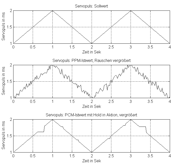
PCM stands for "Pulse Code Modulation". In plain text, an analog signal is sampled and the samples is encoded into a stream of PCM word.


PCM data is relatively immune against noise during transmission because the reciever need only to tell "1" or "0" states of the inputing stream.
Reference: 
High impedance of output

In digital circuit, the output line has usually three states, namely, 0, 1 and high impedance.
In the state of 0 or 1, the output line has a low impedance. When the output in the high impedance state, the output line will be effectively removed from the rest of circuit. In such way, it allows multiple circuits to share the same output line.

Arbiter

Abiter is an eletronic device to determine the order of access to a shared resource, when the resource is almost at the same time requested by several processores.

How SPI works

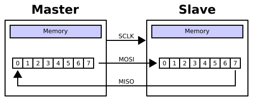
Based on SPI wiki, a short summary of SPI mechimism.

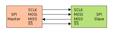
Four logic signals.
  • SCLK — Serial Clock (output from master)
  • MOSI/SIMO — Master Output, Slave Input (output from master)
  • MISO/SOMI — Master Input, Slave Output (output from slave)
  • SS — Slave Select (active low; output from master)


Data transimission:

During each SPI clock cycle, a full duplex data transmission occurs:
  • the master sends a bit on the MOSI line; the slave reads it from that same line
  • the slave sends a bit on the MISO line; the master reads it from that same line

Scanning algorithm for 3 x 4 Keypad Matrix

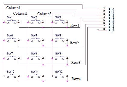
When a keypad is connected with a microprocessor, e.g 8051, a scanning algorithm is used to detect the pressed keys. See shown in [1]


Scanning algorithm
1.       Start.
2.       Make All Pins High.
3.       Make Column 1 pin low.
4.       Check if Row 1 is low, if yes then Switch 1 has been pressed.
5.       Check if Row 2 is low, if yes then Switch 4 has been pressed.
6.       Check if row 3 is low if yes then Switch 7 has been pressed.
7.       Check if row 4 is low if yes then Switch 10 has been pressed.
8.       Make Column 1 Pin high & Column 2 Pin Low.
9.       Check if Row 1 is low, if yes then Switch 2 has been pressed.
10.   Check if Row 2 is low, if yes then Switch 5 has been pressed.
11.   Check if row 3 is low if yes then Switch 8 has been pressed.
12.   Check if row 4 is low if yes then Switch 11 has been pressed.
13.   Make Column 2 Pin high & Column 3 Pin Low.
14.   Check if Row 1 is low, if yes then Switch 3 has been pressed.
15.   Check if Row 2 is low, if yes then Switch 6 has been pressed.
16.   Check if row 3 is low if yes then Switch 9 has been pressed.
17.   Check if row 4 is low if yes then Switch 12 has been pressed.
18.   Make column 3 pin high
19.   Stop
Reference: 
[1]http://www.dnatechindia.com/index.php/Tutorials/8051-Tutorial/Interfacing-Matrix-Keypad-to-8051.html

2010-05-05

What is BSP?

"I think you're referring to the 'Board Support Package'. This usually refers to the OS, and the board-specific drivers in the OS. The BSP is the first thing that must be built in order for an embedded system to work."

2010-04-15

Flash File System

Flash memory is widely used to hold a file system for an embedded device. The following is some facts about flash file system:
  • Flash has two types: NAND and NOR flash. NOR is expensive and allows random-access for reading, NAND is cheap and allows only page access.
  • Flash memory has finite number of erase/write cycles. >100K
  • Flash devices allow programming values from a “1” to a “0”, but not from “0” to a “1” value. To program values back to “1”s requires erasing a full block. The time taken to erase blocks can be significant. In most cases when data is edited it must be written to a new location in flash and the old data invalidated. (Wear levelling)
  • Flash file system types: JFFS2 and YAFFS.
  • Flash file system contains of both code and data. There are two ways to execute the code: Store and Download (SnD) and eXecute in Place (XiP).
SnD (upper) and XiP (lower)
References:

2010-04-01

Timers in Microcontrollers

Timers are indispensable components of microcontroller. These timers are essentially counters that increment based on the clock cycle and the timer prescaler. When the limitation reaches (overflow), a interrupt will be generated. There are several different types timers:

  • watchdog timer, used to reset the controller if a hang of system or unexpected logical conditions occur.
  • 8 bit basic timer, upper limit is 255. Usually for general purpose
  • 16 bit timer, upper limit is 65535, used for PWM and capture/compare function, e.g RC acquisition.
Every timer is configured with a clock source (internal or external) and prescaler. See the example at http://www.societyofrobots.com/programming_timers.shtml:

Assume that Timer1 is set up with a prescaler of 8 on a MCU clocked at 20 MHz. Assume that a total of 6250 clicks were counted.

then . . .

    delay (in ms) = (# ticks) * 4 * 8 * 1000 / (20000000)

    delay (in ms) = (6250) / 625 = 10 ms

where
  • 4: in PIC16 and 18F families 1 instruction cycle = 4 crystal cycle
  • 8: prescaler number
  • 1000: unit in ms
  • 20000000: 20 MHz clock input

Reference:

Watchdog Timers

....To keep a watchdog timer from resetting your system, you've got to kick it regularly

....The hardware component of a watchdog is a counter that is set to a certain value and then counts down towards zero. It is the responsibility of the software to set the count to its original value often enough to ensure that it never reaches zero. If it does reach zero, it is assumed that the software has failed in some manner and the CPU is reset....


Reference:


2010-03-29

RC Acquisition Principle


The RC acquisition method is used to detect the human touch of any capacitive touch by measuring the small variation of the touch electrode capacitance. Electrode capacitance (C) is periodically charged and discharged through a fixed register (R). The capacitance value (C) is calculated by measuring the charge time (t1) the (Vout) voltage requires to reach the threshold (Vth).

In touch sensing applications, the capacitance value (C) is the addition of a fixed capacitance (electrode capacitance, Cx) and the capacitance added by the human finger (touch capacitance, Ct) when it touches or is close to the electrode. Correspondingly, it takes more time (t2) to reach the threshold (Vth) during charge and discharge. The increasing from (t1) to (t2) indicates that a finger has touched the electrode capacitance.

Reference:

2010-03-22

Port microC/OS-II to AVR32 UC3

We should understand that a software can be called kernel must fulfill at least these four tasks:
  • Task management, sometime call it scheduler.
  • Time management, handle timer, delay.
  • Intertask communication, how to share the resource between mutiple tasks.
  • Memory Management, e.g. how to allocation of memory.
However, these functionalities are implemented in a general way, so that it can be used in hopefully all kinds of CPU archtectures. Porting is to finish the rest job, namely, to make the kernel more specific to a certain CPU archtectures with a given toolchain.

Let's see a concrete example: Porting micro C/OS-II to AVR32UC3 microcontroller. The codes in the first block (uC/OS-II book) are the general implementation of kernel, implemented in standard C. If you check the code more closely, you may find that some used functions (or macros) are not yet implemented there. For example:
  • OS_TASK_SW()
The macro is used everywhere to switch context, saving the processor registers of task be suspended and restoring the registers of higher-priority task. The exact implemented is done in OS_CPU.H, you may notice that it is in the porting block (section 3). According to the used toolchains,

For GUN toolchains
  • #define OS_TASK_SW() __asm__ __volatile__ ("scall")

For IAR toolchians
  • #define OS_TASK_SW() (OSCtxSw())
If uC/OS is ported to Intel 80x86 architecture, the macro is defined by assambly instructions
  • #define uCOS 0x80
  • #define OS_TASK_SW() asm INT uCOS
In the graphic, BSP(Board Support Package) codes usually encapulate the utility functions for convenient access or configure the hardwares, e.g. timer, led and so on.

Usually, the porting is provided by vendor of chips, because these guys know it best and want their product as compatible as possible to all kernels.

Reference:

2010-03-19

What does SOC usually have?

System-on-a-chip or system on chip (SoC or SOC) refers to integrating all components of a computer or other electronic system into a single integrated circuit (chip). Usually it consists of

  • One microcontroller, microprocessor or DSP core(s). Some SoCs – called multiprocessor System-on-Chip (MPSoC) – include more than one processor core.
  • Memory blocks including a selection of ROM, RAM, EEPROM and flash.
  • Timing sources including oscillators and phase-locked loops.
  • Peripherals including counter-timers, real-time timers and power-on reset generators.
  • External interfaces including industry standards such as USB, FireWire, Ethernet, USART, SPI.
  • Analog interfaces including ADCs and DACs.
  • Voltage regulators and power management circuits.
Reference:
http://en.wikipedia.org/wiki/System-on-a-chip

RAM, ROM, and Flash Memory

A good explaination about RAM, ROM and Flash is given http://eu.dummies.com/how-to/content/ram-rom-and-flash-memory.html . A exmplaination with more detail is given at
http://www.escotal.com/memory.html.

RAM: Stands for random access memory; refers to memory that the microprocessor can read from and write to. When you create something in memory, it’s done in RAM. RAM is memory and vice versa.

ROM: Stands for read-only memory. The microprocessor can read from ROM, but it can’t write to it or modify it. ROM is permanent. Often, ROM chips contain special instructions for the computer — important stuff that never changes. The microprocessor can access information stored on a ROM chip whenever it needs to. The instructions are always there because they’re not erasable.

Flash: A special type of memory that works like both RAM and ROM. You can write information to flash memory, like you can with RAM, but that information isn’t erased when the power is off, like it is with RAM.


Reference:

2010-03-17

AT32AP7 is dead

Max just came back from "Embedded world 2010", with several evaluation board samples from hardware vendors. The biggest gift this year is a piece of development package from Atmel: AVR32EVK1100 board with a AT32UC3A0512 microcontroler, which cost more than 100 euro if you buy it.

He browsed the attached CD and surprisedly found that almost half doc introduced another series AT32AP7***. Maybe it is a parent series of AT32UC3, it is first guess of Max. After googling for some time, he realized that the AT32AT7 is dead and not recommanded for new design.

An important lesson: check the homepage of vender at first, which status is your chip, before you are going to use it.

References:

2010-03-16

AVR vs ARM

AVR and ARM are two kinds of CPU archtectures. A comparison between AVR32 UC3 and AMR7 is shown below:

Knowledge Items for Embedded System

If you want to do something related hardware and drive development, I have some advise to you :
  1. you should study C well. Though some time we use assembly language, C is main and used mostly.
  2. you at least be familiar with a microcontroller, whatever a AVR MCU, or a ARM MCU. You should know it's basic principle and function, such as interrupt mode, clock management, power management etc.
  3. know some general devices' Operating mode and protocal, such SPI, USB, DMA, SDCard, etc. It's useful to develop application later, in different MCU, these devices' hardware maybe different, but there are similar principle and protocal.
  4. then you can study some things about RTOS, such as ucos, freertos, etc. It's useful to design some multitask and real-time projects.

But if you want to develop embedded application base on embedded OS, you can:
  1. study something about bootloader, it will help you to understand the startup of the system.
  2. choose a embedded OS to start, linux or WinCE, this depends on youself. But no matter which OS, you have to spend a lot of time to study.
  3. you'd better to know how to build a OS, and develop driver base on a OS.

Reference:
http://www.programmersheaven.com/mb/embedded/393622/394143/re-avr-or-arm-microcontroller-for-starting/?S=B20000